Principle of Operation:
This circuit operates on the principle of multi-stage power amplification consisting of pre amplifiers, drivers and power amplification using MOSFET. The pre amplification is done using a differential amplifier, driver stage is the differential amplifier with current mirror load and power amplification is done using MOSFET class AB operation. MOSFETs have an advantage over BJT in having a simple drive circuit, being less prone to thermal stability and having high input impedance. A pre-amplifier consisting of a two stage differential amplifier circuit is used to produce a noise free amplified signal. First stage of the pre-amplifier consists of a differential mode emitter coupled amplifier using PNP transistors. The second stage consists of a differential amplifier with active load, so as to increase the voltage gain. The current mirror circuit actually ensures the output current to remain constant irrespective of the changes in input signal voltages. This amplified signal is then given to the push pull amplifier stage, which produces a high power output signal.
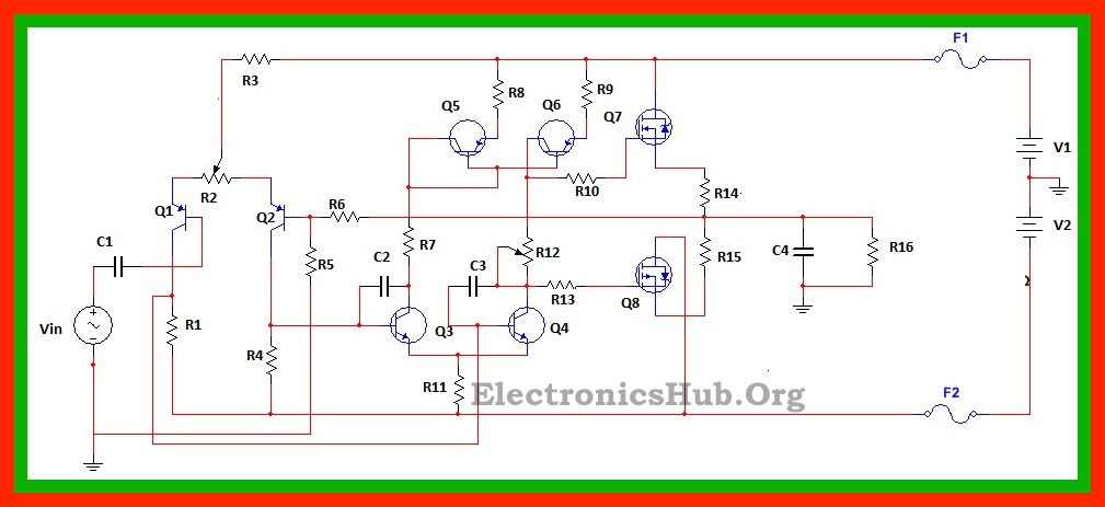
100W MOSFET Power Amplifier Circuit Diagram:
R1, R4: 4k ohms R2: 100 ohms R3: 50k ohms R5: 1k ohms R6: 50k ohms R7: 10k ohms R8, R9: 100 ohms R10, R13: 470 ohms R11: 100 ohms R12: 3k ohms R14, R15: 0.33 ohms C1: 10uF C2, C3: 18pF C4: 100nF Q1, Q2: BC556, PNP transistors Q3, Q4: MJE340, NPN transistors Q5, Q6: MJE350, PNP transistors Q7: n channel E-MOSFET, IRF530 Q8: p channel E-MOSFET, IRF9530 V1, V2: +/- 50 V.
MOSFET Power Amplifier Circuit Design:
Here we select N channel MOSFET IRF530 and P channel MOSFET IRF9530 as power amplifiers. For a power of 100w and load of 8 ohms, required output voltage is about 40V and output current is about 5A. This gives the value of source resistors to be around 0.33 ohms and the current drawn by each MOSFET to be around 1.6A (output voltage/(pi multiplied by load resistance)).
100W MOSFET Power Amplifier Circuit Operation:
PNP transistors form the differential amplifier circuit where one of the transistors receives the input AC signal and the other transistor receives the output signal through feedback. The AC signal is coupled to the base of Q1 through coupling capacitor and feedback signal is fed to the base of Q2 through R5 and R6. The output of the amplifier is set by adjusting the potentiometer. The output from the first stage differential amplifier is fed to the input of the second stage differential amplifier. When input voltage is more than the feedback voltage (in case of the first differential amplifier), the voltage inputs to the transistors Q3 and Q4 of the second differential amplifier simultaneously differs from each other. The transistors Q5 and Q6 form the current mirror circuit. This current mirror circuit ensures the output current flowing to the push pull amplifier circuit to remain constant. This is achieved because when collector current of Q3 increases, the collector current of Q4 decreases to maintain a constant current flowing through the common point of the emitter terminals of Q3 and Q4. Also the current mirror circuit produces an output current equal to the collector current of Q3. The potentiometer R12 ensures the application of proper DC biasing to each MOSFET. Since the two MOSFETs are in complementary to each other, when a positive voltage is applied to the gate of Q7, it conducts. Similarly for a negative threshold voltage, Q8 conducts. The gate resistors are used to prevent the MOSFET output from oscillating. The input to the circuit is given by a 1khz AC input voltage of 4Vp-p. An oscilloscope is connected such that channel A is connected to input and channel B is connected to output. The power at the load is observed by connecting a wattmeter to the load.
Applications of 100w MOSFET Power Amplifier Circuit:
Comment * Name * Email * Website
Δ
![]()
![]()
![]()
![]()
![]()

