Here i am going to explain different ways of building adjustable timer circuits. However, these methods are cost ineffective.Three circuits are explained here are 1)Simple adjustable timer using 555 IC,2)A cyclic on/off timer using 555 IC,3)Adjustable timer using arduino. (40+ Simple 555 Timer Circuits & Projects)
Simple Adjustable Timer Circuit with 555 IC
Using simple 555 timer we can design an adjustable timer switch. This circuit is flexible to adjust required time.
Circuit Diagram
Components
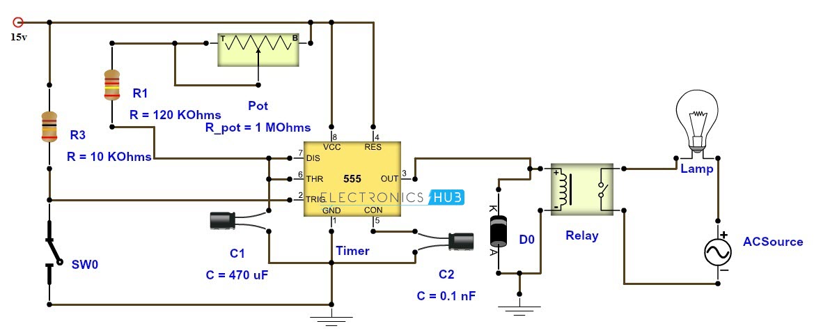
555 timer Electrolytic capacitor – 470 uf ceramic capacitor – 0.1nF Resistors 120k ohm 10k ohm Relay -12v Push button
Working
Here 555 timer is operated in monostable mode. When the trigger input is applied,555 timer produces a pulse. This pulse width depends on R and c values. The above proposed circuit is a 1-10 minute timer.When Pot is minimum it gives 1 minute delay,where maximum value of pot can produce 10 minutes. Time period can be calculated using formula
T=(R1+R2)*C1.seconds
When Pot is maximum R is 120K+1.1M ≈ 1.2M (approximately) and C1=470uf
T= 1.2M*470uF = 620 seconds≈10 minutes.This is the maximum time.
For minimum time place the pot in least position.Then R= 120k Hence time T=120k*470uf=6 2 seconds~1 minute (approximately). A 12v relay is used to drive the ac load connected at the output. Thus relay will be on for required amount of time set by the user using pot and then it is switched of automatically. This circuit is used in such applications where the load is switched on for sometime and is off for rest of the time.
Note
To prevent 555 timer from flyback current in the relay use a diode before the relay. Some 555 versions may get damaged because of this.
[Also Read: 12V Time Delay Relay]
Adjustable ON OFF Timer(using 555 astable mode)
In this circuit a timer with cyclic on off operations is designed. This circuit uses very basic components like 555 timer and 4017 counter. These on off intervals can be adjusted by varying the 555 timer output and number of counter outputs. Let us discuss in detail about this circuit.
Circuit Diagram
Components
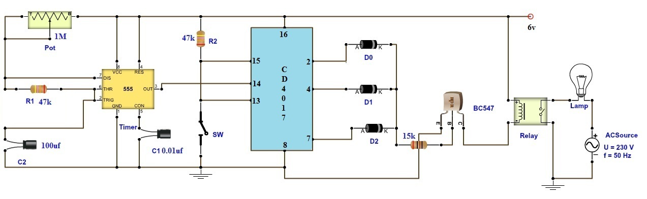
R1 and R2 – 47 KΩ R3 – 15K Ω VR1 – 1M Ω C1 100µF C2 0.01µF C3 0.1µF Diodes 555 Timer IC CD4017 IC BC 148 B Transistor 6 V/ 100 Ω SPST Relay
Working
When the power supply is given ,555 timer produces square wave at pin 3 as it is in astable mode. It gives a pulse width according to value of pot. It can be calculated as
T( high) =0.693*(R1+R2)C 1 T(low) =0.693R1*C1
This square wave is given to CD4017 IC decade counter which has 10 outputs activated sequentially upon a given clock input. The outputs of the decade counter drive the transistor into active mode so that relay coil will be energized. (Instead of 6v relay one can use 12v relay also but relay should be applied with 12v instead of 6v.) Here the length of ON-time of the load is a multiple of 555 timer period output and number of outputs used in CD4017. Suppose in this circuit 3 outputs of CD4017 are used.So,On time of load is 3 times of T (high) and off time is 9 times of T(high). Therefore, ON and OFF can be varied for desired duty cycles by appropriately connecting the pins of decade counter. It is also possible to add a sensor or switch at reset input of decade counter for automatic turning off the load in emergency or needy (for an automatic operation) situations.
Application
Let us understand the application of this circuit. For example in air coolers,there is a pump that pumps water to the mat.This need not be switched on continuously . It can be ON until cooler mats are wet and then it can switched off.Again when they are dry it should pump the water. Suppose if there is adequate water in the tank, the pump must be turned off automatically. This can be achieved by adding a level sensor such that this sensor input drives the reset and inhibit pins towards the ground potential. This circuit is used in such applications where cyclic operation is required.
If very long time delays are required it is not advisable to use 555 timer.Instead one can use a microcontroller. Here is timer using arduino which is user friendly.
Adjustable Timer(Using Arduino)
Arduino adjustable timer is simple circuit to generate timer for required time. This is used to switch on the loads for the certain time period and then they are automatically switched off. Here arduino plays a key role in setting this time period. Here a relay is used to switch the load for certain amount of time.
Circuit Diagram
Components
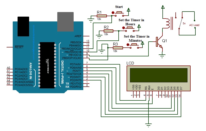
Arduino Board LCD Push buttons Relay
Working
Initially when the circuit is switched LCD will display ” adjustable timer”. Now using the two buttons set the timer.Button connected to 8th pin is used to set the timer in minutes and button connected to 10th pin is used to set the timer in hours. Set the time by pressing these buttons.When the button is pressed , time is incremented every time. Now click on start button to switch the load. When the time is completed load is switched off automatically. To set the timer next time click the reset button on the arduino and set the timer again.
Project Code
Applications of Adjustable Timer
There are numerous real time operations which require time scale switching loads. Some of these are listed below. 1.Cooler controllers 2.Irrigation pump control 3.Exhaust fan switching 4.Industrial repetitive switching of loads 5.Load shedding and control 6.Automatic lubrication tools 7.Traffic lights control 8.Printing applications, etc. I am interested in the first circuit, Is it really 15 Volts to power the 555 ic or is there a missing decimal? Thanks again. Hello, Is it possible to re configure the circuit to make it turn off, after the time delay has run, even though the start switch is still open. Will be used in a simple alarm system. Thank yo THANK YOU VERY MUCH THANK YOU VERY MUCH Comment * Name * Email * Website
Δ
![]()
![]()
![]()

![]()
![]()

