When power supply is turned OFF, the circuit senses the day light and according to the light it turns on the LED’s. If the light is present even though power fails the circuit turns OFF the LEDs. Here LDR (Light Dependent Resistor) is used to sense the light.
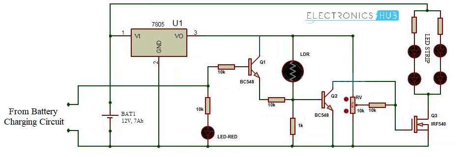
Automatic Emergency Light Circuit Principle When power supply is available, battery charges through the battery charging circuit. When the power fails, the white LED’s which are connected MOSFET will glow based on the light condition till the battery shuts down. When LDR (Light Dependent Resistor) is in light, the resistance of LDR is very low. As a result base of the transistor Q2 becomes high. As a result white LED’s which are connected to MOSFET turns OFF. When the circuit is in dark, the resistance of LDR is in order of mega ohms. Now the base of the transistor becomes low, as a result transistor Q2 switches the white LED’s to ON state.
Automatic Emergency Light Circuit Diagram
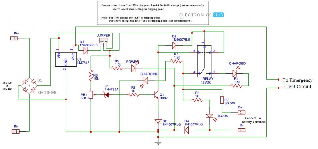
I have divided the circuit into two parts. The first one is the battery charging circuit which also acts as an indicator circuit if the mains supply is shut down. The second circuit is the emergency lights circuit using LEDs. Based on the mains supply and the lighting conditions, the emergency LEDs are turned ON or OFF. Battery Charging Circuit
The components, working and connections are explained in this Lead Acid Battery Charger Circuit. Coming to the Automatic LED Emergency Light Circuit, the following is the circuit diagram.
Components for Automatic LED Emergency Light Circuit
7805 voltage regulator Light Dependent Resistor – 2MΩ IRF540 MOSFET BC548 NPN Transistor Pot – 10KΩ High bright LEDs – 3V@15mA Red LED – 1 10KΩ Resistors – 3 1KΩ Resistor – 1
Working of Automatic Emergency Light Circuit
Initially, when the mains power is active, the battery charging circuit will charge the battery. In case the mains power is shut down, the battery charger circuit indicates the Emergency Light circuit about mains power and activates the emergency lights circuits through the battery. Instead of immediately turning ON the LEDs, it first reads the ambient lighting through the LDR and then if the lighting is low, the LEDs are turned ON.
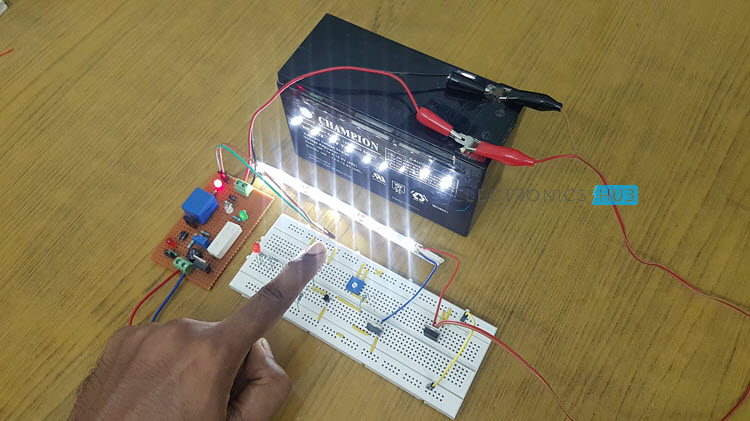
How to Operate Automatic Emergency Light Circuit?
Advantages of Automatic Emergency Light Circuit
This is very simple circuit and the cost is also very less. Power is saved because the circuit switches the LEDs based on light conditions
Automatic Emergency Light Circuit Applications
Used in child’s study rooms to avoid the sudden power failure. As an emergency lamp in homes. Used in security systems to switch ON the lights automatically during the power failure.
Emergency Light With Battery Charger
A very easy circuit of “variable power supply and charger” is being explained here. It is not only very much useful in the time of power cut but also used as main power supply. At your workbench, you can use this circuit to check or testing of your electronic projects. Mobile phone batteries can be charged with the help of these circuits. This circuit can work as an emergency light.
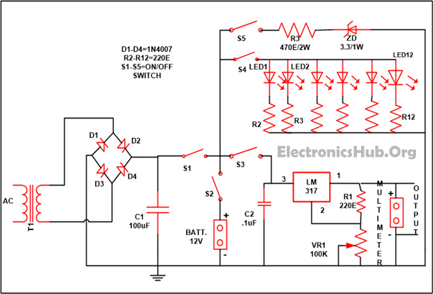
Circuit Diagram
Circuit Components
LM317 – 1 Resistor R1 (220E) – 1 R2-R12 (220E) – 11 R13 (470E) VR1 (100K) – 1 C1 (100uF) – 1 C2 (. 1uF) – 1 D1-D4 (1N4007) – 4 S1-S5 (on/off switch) – 5 LED1-LED12 – 12 Transformer – 1 Battery – 1 Zener diode (3.3) – 1
Components Description
Working of Mobile Phone Battery Charger Circuit
As per your need you can take the output from the circuit by just flipping the different number of switches (from S3, S4 and S5) in the circuit. If you require the variable power supply as your output than set switch S3 into “on” state. LM317 is used in the circuit which is a variable voltage regulator to supply variable power. The LM317 is basically positive voltage regulator has three terminals. 1.2 V to 37V is the range of the output voltage that is provided by the LM317. Different range of voltage can be achieved by just adjusting the variable resistor that is provided in the circuit and with the help of multimeter output can be seen and the voltage which is desirable can set. The power supply range can altar from 1.5V to 12V. With the help of flipping the S5 switch which is provided in the circuit Li-ions battery can be charged, which are generally used in the mobile phones with the assist of your mobile connectors. While the charging current in the circuit is being controlled with the help of resistor R13. Turn over to switch S5 if you want to use the emergency light. Reflectors can be used in the circuit if you wish to enlarge the intensity of light. S1 and S2 are the two switches that are given in the circuit so that you can power your circuit either directly with the AC supply or else you can take help of any battery. If you want to use an AC supply than flip to switch S1 while if you want to have supplied from the battery than flip to switch S2. In the place of AC power supply solar panels can be used and for storing the charge you can take rechargeable batteries, this will not merely save electric bill but also assist you a LED Base Automatic Emergency Lighting system using LDR and a 6 volt battery. thanks Comment * Name * Email * Website
Δ
![]()
![]()
![]()
![]()
![]()

