We turn on the lights in our washroom when we enter it and turn them off when we leave. Sometimes, we forget to turn the lights off after leaving the washroom. This may lead to power wastage and also the lifetime of the light bulbs may decrease. To avoid these problems, I will show you how to make a simple circuit which will automatically turn the lights on when a person enters the washroom and it automatically turns it off when he/she leaves it. By automating the process this way, there are many advantages like, the person need not care about turning the light on or off whenever he/she is using the washroom. The circuit, which you will know about in a moment, does it automatically for that person. The circuit is also designed to consume lesser power so that the circuit can be used in any household or public washrooms without worrying about the power bill.
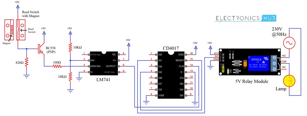
Automatic Washroom Light Switch Circuit Diagram
Components Required
Reed Switch with Magnet (available as combination) LM741 Op-Amp IC CD4017 Decade Counter IC 5V Relay Module Lamp BC558 PNP Transistor 2 X 10KΩ Resistor 100Ω Resistor 820Ω Resistor Connecting wires Mini Breadboard 5V Power Supply
A Brief Note on Reed Switch
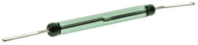
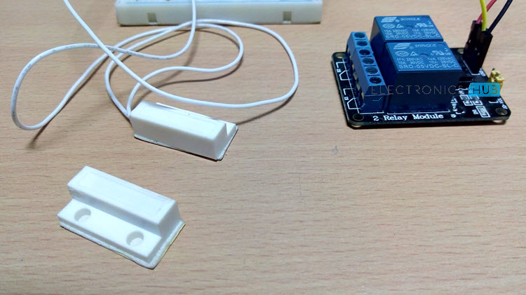
Reed Switch is one of the important components of this circuit and in fact the element which is used to detect the opening and closing of the door in this project is a reed switch. The following image shows a typical reed switch.
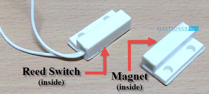
A Reed Switch is a magnetically operated switch. It contains a magnetic sensitive switch, which when subjected to a small magnetic force, will either close or open (depending on its construction). There are two types of reed switches. One type with Normally Open Contact and the other with Normally Closed Contact. The Reed Switch used in this project is shown below. You cannot see anything as it is placed in a housing but the part with wires is the Reed Switch and the other part consists of a magnet.
This is a Normally Open NO type switch i.e. usually the switch is open and when a magnet is placed near the switch, it will be closed. Reed Switches are mainly used in detecting whether door is open or not. It can also be used as a proximity sensor.
Circuit Design
The first important component is the LM741 Op-Amp. It is being operated in comparator mode. Pin 2 is the inverting input of LM741 and its input is given from two 10KΩ Resistors. One end of the Reed Switch is connected to +5V supply while the other end is connected to base of a PNP Transistor (BC558). Also, the base of the transistor is pulled down with the help of a resistor. The emitter of the transistor is connected to the Non-inverting input of the Op-Amp while the collector of the transistor is connected to +5V.
Pin 1 of LM741 i.e. its output is connected to the CLK input of CD4017 i.e. its Pin 14. Pin 2 of CD4017 is connected to the input of the relay while Pin 4 is connected to Pin 15. Rest of the connections can be easily understood from the circuit diagram. WARNING: If you are planning to use a real light bulb that runs on AC Supply, be extremely careful when connecting it to the relay and providing the mains supply.
Working
Before continuing with the working of the circuit, I will first explain the intended setup of this circuit. The reed switch is fixed to the wall near the door while the magnet is fixed to the door. This means that the reed switch will always be in closed state as the door is closed when the washroom is not in use (which is assumed as starting point) and the magnet will be near the switch. Assume you opened the door and entered into the washroom and then closed the door behind you. This action will make the switch open (when the door is opened first) and close (when you close the door). As a result, the output of the Op-amp goes HIGH (when you open the door)and then goes LOW (when you close the door). This in turn will cause the counter to produce a HIGH output at its Pin 2. Since Pin 2 of CD4017 is connected to the relay, the light will be turned ON.
Now, when you are done with your business in the washroom, you will once again open the door, come out of the washroom and close the door. This action will once again cause the same action i.e. switch will open and close and output of Op-Amp will become HIGH and then LOW. But, since the Pin 4 of CD4017 is connected to the Reset pin, all the outputs will become LOW and hence the relay will be turned OFF, which in turn switches off the light.
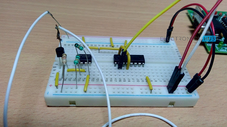
Operation of the Circuit
Read the following posts also:
Automatic Railway Gate Controller with High Speed Alerting System Auto Night Lamp Using High Power LED
It you choose output 1 then you will have two states, The ON STATE and the OFF STATE. (1, 0)
- Where do I put in the power supply? Will it be DC? What should be the voltage?
- I can see two arrow-type components (somewhat like two gates) in the circuit, pointed upwards. What are those? WARNING: If you are planning to use a real light bulb that runs on AC Supply, be extremely careful when connecting it to the relay and providing the mains supply. .1) sometimes relay gets automatically switch on or off without any door movement.
- there are other switches in my bathroom like exhaust fan, geyser etc. sometimes when i switch on any of these switches relay gets signal & turn the light on/off. (Note:- i have used adopter to give 5 V to circuit & adopter(230 v AC to 5 V DC) is connected to same board where other switches are. Comment * Name * Email * Website
Δ
![]()
![]()
![]()
![]()
![]()

