Introduction
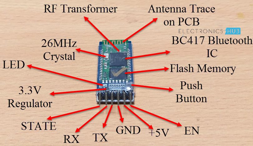
There are a lot of basic circuits in Electronics that might look simple on paper but serve a big purpose practically. One such circuit is the Voltage Divider Circuit or sometimes known as the Potential Divider Circuit. Before going further into the understandings of a Voltage Divider Circuit, let us first take a problem and see how can we resolve it with the help of a Potential Divider. Consider a Microcontroller that runs on 5V power supply. For the sake of simplicity, let this Microcontroller be Arduino (and the ATmega328P on Arduino Uno board requires a 5V power supply). Now let us assume you want to implement a project that involves a Bluetooth Module (like Bluetooth Controlled Home Appliances or Bluetooth based DIY Robotic Arm). One of the commonly used Bluetooth Modules for DIY projects is HC-05.
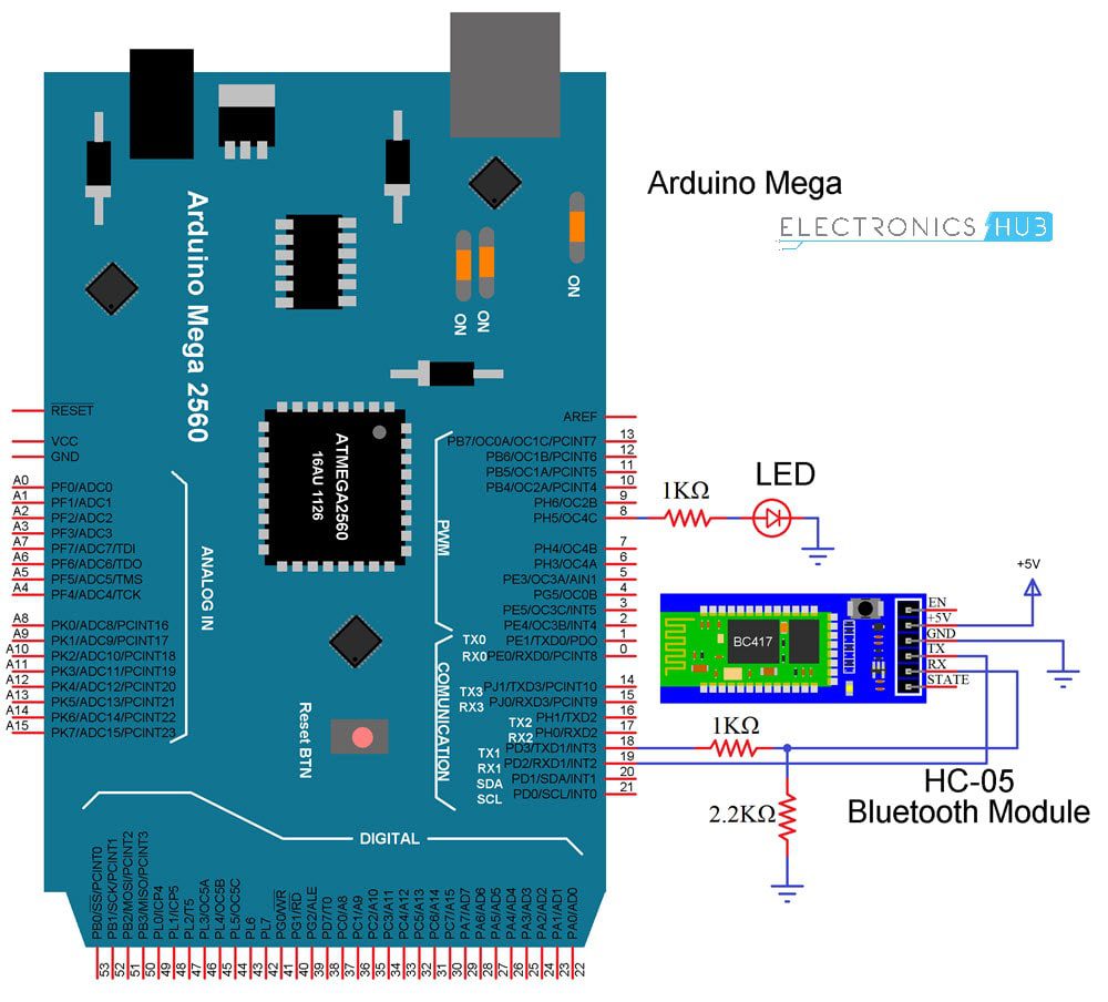
The HC-05 Bluetooth Module can be connected to Arduino Uno using UART Communication i.e. Pins 0 and 1 of Arduino Uno (RX and TX respectively). These pins should be connected to corresponding TX and RX pins of the HC-05 Bluetooth Module. But there is a problem here. If you have used this module earlier or seen one of our projects implemented using this module, then you might be familiar with its power ratings i.e. it works on 3.3V power supply. This means that that the RX and TX pins of HC-05 work on 3.3V level. Note that some HC-05 Modules can be powered by 5V supply as they have an on-board 5v to 3.3V Regulator. But this is limited to the power supply and the communication pins i.e. RX and TX still work at 3.3V level. This means that we cannot directly connect the Arduino Uno and HC-05 Bluetooth Module using their UART pins as the 5V output of the Arduino Uno’s TX (which has to be connected to the 3.3V RX pin of HC-05) might damage the peripheral or worse it might completely destroy the module. Note that the TX of HC-05 Bluetooth Module can be connected to RX of Arduino Uno directly as the output of HC-05 Module’s TX is 3.3V and Arduino Uno will not have a problem with that. The problem is only with the other way i.e. 5V TX of Arduino Uno to 3.3V RX of HC-05. So, we must first convert the 5V signal from Arduino Uno’s TX pin to 3.3V level and then connect it to the RX pin of HC-05 Bluetooth Module. This is where a simple Voltage Divider Circuit comes in handy.
What is a Voltage Divider Circuit?
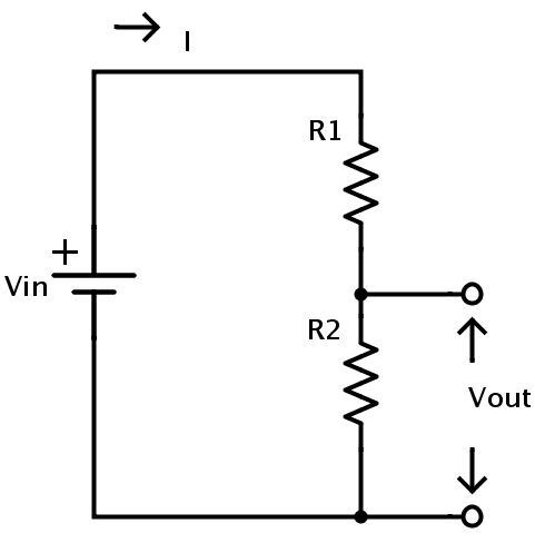
A Voltage Divider Circuit or a Potential Divider Circuit is a simple electronics circuit that converts a higher input voltage to a lower output voltage just by using a couple of resistors. It is often used in analog circuits like Op-Amp based circuits for example, where the required voltage may be variable. The following image shows as a simple Voltage Divider Circuit consisting of two resistors R1 and R2. VIN is the input voltage while VOUT is the output voltage taken across the resistor R2.
Thus, just by using two resistors R1 and R2, we can convert any input voltage VIN to any desired output voltage VOUT by appropriately choosing the values of R1 and R2.
Voltage Divider Equation
The formula for calculating the output voltage VOUT of a voltage divider network is given below: VOUT = (VIN * R2) / (R1 + R2) Where, VIN = Input Voltage VOUT = Output Voltage R1 and R2 values of two resistors. From the above equation of the Voltage Divider formula, we can confirm that the scaling factor for the output voltage is determined by the ratio R2 / (R1 + R2).
Deriving Voltage Divider Equation
The basis for the voltage divider circuit is the Ohm’s Law. In fact, we can derive the voltage divider equation simply by using the Ohm’s Law. We know according to Ohm’s law that current flowing in a circuit is directly proportional to the voltage to potential different across the circuit. In the above statement, the proportionality constant is the resistance of the circuit (or component). Using Ohm’s Law in the above circuit, we can calculate the input voltage as VIN = I * R1 + I * R2 = I * (R1 + R2) Similarly, the output voltage is VOUT = I * R2 If we observe the above two equations, it is clear that the current is same in both the equations and hence we can re-write the above equations as follows: I = VIN / (R1 + R2) and I = VOUT / R2 Equating the above two equations, we get VOUT / R2 = VIN / (R1 + R2) Finally, VOUT = VIN * R2 / (R1 + R2)
Example
Let us see an example for the voltage divider equation. Let VIN be 5V and the values of R1 and R2 are 10000 Ω (10 KΩ) and 20000 Ω (20 KΩ) respectively. From the above given equation, we can calculate the value of VOUT as follows: VOUT = 5 * 20000 / (10000 + 20000) VOUT = 3.3V This combination of R1 as 10 KΩ and R2 as 20 KΩ is one of the commonly used voltage divider circuits to convert a 5V level signal to a 3.3V level signal.
Applications
Voltage Dividers are quite commonly used in analog as well as digital circuits. Some of the common applications of Voltage Divider Circuits are mentioned below.
Level Shifters
One of the main applications of a voltage divider is to act as a level shifter. As already mentioned in the introduction, if the Microcontroller and a sensor are working at different voltage levels, then a simple level shifter consisting of a couple of resistors configured in Voltage Divider fashion will do the job.
A typical requirement is to convert a 5V signal from a Microcontroller to a 3.3V signal for the sensor. We can do this by simple using two resistors of 10 KΩ and 20 KΩ as R1 and R2. NOTE: 20 KΩ resistor is not common and you can used two 10 KΩ resistors in series. An alternative is to use 1 KΩ resistor as R1 and a fairly common 2.2 KΩ resistor as R2. In this case, the output voltage will be 3.4 V but it will be tolerable by the sensor.
Potentiometers
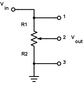
Potentiometer or simply a POT is a variable resistor with three terminals. Using a potentiometer, you can implement a Voltage Divider circuit with variable output voltage. You can achieve this by connecting the input voltage across the extreme pins of the potentiometer and taking the output across the wiper terminal.
By adjusting the position of the wiper of the potentiometer, the output voltage also varies.
Resistive Sensors (LDR and Thermistor)
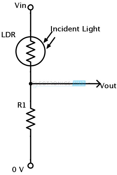
Two of the commonly used sensors in DIY Projects are LDR (Light Dependent Resistor) and Thermistor. Both these sensors are of resistive type. But the problem is that a Microcontroller like Arduino for example, will only read Voltages at the input.
By connecting the resistive sensors (LDR or Thermistor) in a voltage divider circuit, you can obtain the voltage across the sensor and program the microcontroller to scale the value accordingly. Comment * Name * Email * Website
Δ
![]()
![]()
![]()
![]()
![]()

