Introduction
Electronic eye is also called magic eye. As the automation is an emerging technology these days, just imagine a door bell that automatically rings when a person visits your home. This also provides security when any person is trying to enter into your home without your permission. Electronic eye is a simple electronic device that continuously watches if anyone is visiting your home.
This project presents the circuit of electronic eye. Before going to know complete details about this circuit, get an idea about Light Activated Switch Circuit using LDR.
Electronic Eye Controlled Security System Circuit Principle
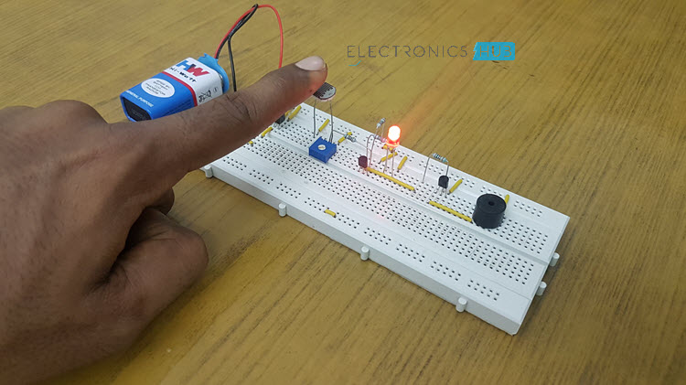
The main principle of the circuit is to ring the door bell when there is any person at the entrance. In order to detect a person, an LDR is used as the sensor. Light on the LDR determines whether a person is present or not. When there is any object at the entrance, LDR is in dark and buzzer starts ringing and the LED starts glowing.
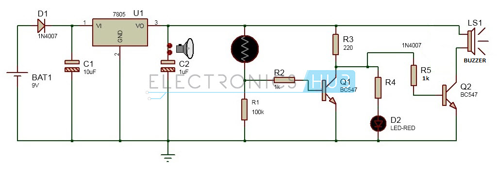
Circuit Diagram of Electronic Eye Controlled Security System
NOTE: Resistor R4 is 220Ω.
Circuit Components
7805 Regulator Resistors – 220Ω x 2, 1KΩ x 2, 100KΩ 1N4007 PN Diode Capacitors – 1µF, 10µF Transistors – BC 547 x 2 Light Dependent Resistor (LDR) Buzzer LED Bread board Connecting wires 9V battery
Electronic Eye Controlled Security System Circuit Simulation Video
Electronic Eye Controlled Security System Circuit Design
This circuit can be divided into two parts. One is the power supply and the other is the logic circuit. In the power supply circuit, a 9V supply from a battery is converted to the 5V .The logic circuit operates the buzzer and an LED when any shadow falls on the LDR.
Design of Power Supply Circuit
Power supply circuit consists of battery, diode, regulator and capacitors. Initially a 9V battery is connected to the diode. Diode used here is a simple P-N junction diode of 1N4007 series. In this circuit, 1N4007 is connected in the forward bias condition.
The main purpose of the diode in this circuit is to protect the circuit from reverse polarity i.e. to protect the circuit if by any chance the battery is connected in reverse polarities. So, the P-N junction diode connected in the forward bias allows the current to flow only in one direction and thus the circuit can be protected. There is some voltage drop across the diode. A voltage of 0.7V is dropped across the diode. A regulator is used for regulating the output voltage of the circuit .The regulator IC used here is 7805. 78 represents the series and 05 represents the output voltage. Thus a voltage of 5V is produced at the output of the regulator. Two capacitors are used before and after the regulator. These two capacitors eliminate the ripples. Thus a constant voltage is produced at the output of the regulator, which is applied to the logic circuit.
Design of Logic Circuit
The logic circuit mainly consists of Light Dependent Resistor, transistors, a buzzer, an LED and a few passive components. A 100KΩ resistor is connected in series to the LDR in a voltage divider fashion. Light dependent resistor will have resistance in mega ohms when it is placed in the dark. This resistance value will decrease gradually when it is placed in the light. Thus, there is a variation in the series resistances. When the LDR is in dark it has high resistance and produces the logic high value at the output. When the LDR is in light, the resistance value of the LDR decreases and at the output it gives logic low voltage. The output of the voltage divider is fed to a transistor which inverts the input from the LDR. The second transistor drives the buzzer. The diode is placed for protection. Buzzer used here is a 5V magnetic buzzer. It has two pin at the output. One pin is connected to the supply and the other pin is connected to the Collector of the second Transistor. LED is used for indication only. When the output from first transistor is high, the buzzer starts ringing. Led is also turned on.
How to Operate the Electronic Eye Controlled Security System Circuit?
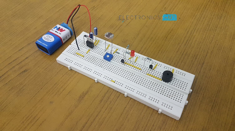
Initially, connect the circuit as shown in the circuit diagram on a bread board. Now connect the supply voltage of 9V using a battery. Place the Light Dependent Resistor in light. You can observe no sound is produced from the buzzer. Place the LDR in dark and the buzzer starts making sound. Also the LED connected to the buzzer will be turned ON. As the intensity falling on the LDR increases sound produced by the buzzer increases.
Electronic Eye Controlled Security System Applications
This can be used in door bell circuits. This can be used in garage door opening circuits. Electronic eye can be used in security applications.
I will appreciate some idea’s Thank You.
- Sir can we use other voltage regulator in the place of 7805 voltage regulator. 2) what happen if we increase or decrease the value of capacitor instead of 10 and 1 micro farad. 3) sir what happen if we use PNP transistor in the place of NPN transistor. 4) sir in the given circuit what is the function of resistor R2,R3,R4,R5. Comment * Name * Email * Website
Δ
![]()
![]()
![]()

![]()
![]()

