Exclusive-NOR Gate
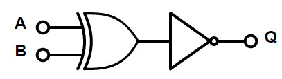
The operation of Exclusive NOR gate is reciprocal to the Exclusive OR gate’s operation. As the basic AND gate implements the Boolean addition , while OR gate implements Boolean multiplication and NOT implements inversion function , there is no such Boolean function defined by the XNOR.This can be derived by basic gates (AND , OR ,NOT).Below shows the diagram of EX-NOR constructed from EX-OR gate.
The logic symbol and Boolean expression for the XNOR gate is shown below.
Ex – NOR gate Logic Symbol and Boolean expression
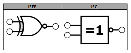
There are multiple standards for defining an electronic component. Generally we follow IEC (International Electro-technical Commission) standards and IEEE (Institute of Electrical and Electronics Engineers). The XNOR logic symbol in IEEE and IEC standards is shown below.
It is a Hybrid gate, the Boolean expression of output of XNOR gate is given as below
The XNOR output is represented as
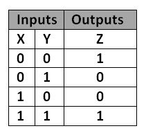
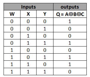
XNOR Truth table
If we observe the operation of XNOR gate, we can say that the XNOR gate output will be HIGH when both the inputs are not same and will become LOW for different combination of input. This we can see in truth table.
Back to top
X-NOR Gate using Basic logic gates
If a specific gate is not available directly, we can design the gate by connecting multiple gates together. An EX-NOR gate can be designed by using basic logic gates like NAND gate and NOR gate.
Using NOR Gates
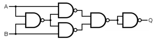
Using NAND Gates
Using NAND and OR Gates
Ex – NOR Gate Pulsed Operation
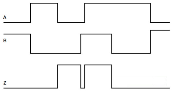
The pulsed operation of 2 input XOR gate is shown below.
Initially when one of the two inputs of the XNOR gate is low, so the output is at low level. When both the input changes to low level, the XNOR output will rise to HIGH level and again when one of the inputs comes to low level, the output also comes to low level. Back to top
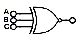
3-input Ex-NOR Gate
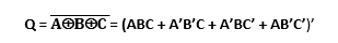
We can have XOR gate with more than 2 inputs, in some cases. The Boolean function is same for the 3- input XNOR gate is
3-Input Ex-NOR gate logic symbolTruth table
For Exclusive NOR gates, we can have the HIGH input when even numbers of inputs are at HIGH level. So the 3-input XNOR gate is called as “Even functioned OR gate”.The truth table and logic symbol for 3-input XNOR gate is given below.
Back to top
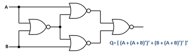
Ex-NOR Function Realization using NOR gates
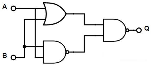
If A and B are inputs and Q is the output of XNOR gate then Q= A XNOR B = (A XOR B)’ Q’= (A XOR B) = A’B + AB’ = A’B + AB’ + AA’ + BB’ = (A + B) (A’ + B’) Q’= A’ (A + B) + B’ (A + B) Take compliment Q= (A’ (A + B) + B’ (A + B))’ = (A’ (A + B) )’ . (B’ (A + B))’ = (A + (A + B)’). (B + (A + B)’) Take compliment again Q’= ( (A + (A + B)’). (B + (A + B)’) )’ = (A + (A + B)’)’ + (B + (A + B)’)’ Take compliment again Q= [ (A + (A + B)’)’ + (B + (A + B)’)’ ]’ Now we can implement the XNOR circuit using NOR gates
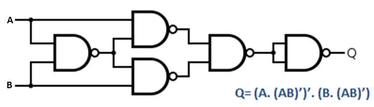
Ex-NOR Function Realization using NAND gates Q= (A XOR B)’ = (A’B + AB’ = A’B + AB’ + AA’ + BB’)’ = ((A + B) (A’ + B’))’ Now we need to implement this circuit using NAND gates Q= ( (A + B) (AB)’ )’ = (A . (AB)’ + B. (AB)’)’ Taking compliment Q’= A. (AB)’ + B. (AB)’ = (A. (AB)’). (B. (AB)’) Taking compliment again Q= (A. (AB)’)’. (B. (AB)’) Now we can implement XNOR gate using NAND gates
Back to top
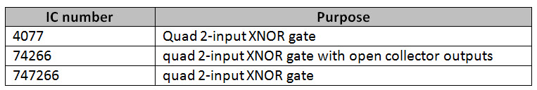
Commonly available TTL and CMOS logic Ex-NOR gate IC’s
Some of the most used XNOR logic ICs are listed below
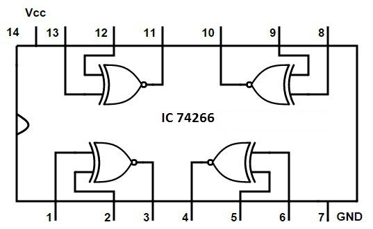
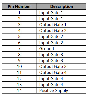
74266 Quad 2-input Ex-NOR Gate IC
Pin description:
Back to top
Ex-NOR gate applications
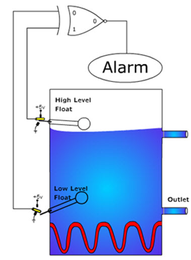
This is also used as Heat exchanger tank, which will ring the alarm when the water temperature level goes up or down, to the pre-set level. The Heat exchanger circuit is explained below.
Construction:
This circuit is used to warm the water. It has two outlets and two float indicators. The float indicators are connected as the inputs of XNOR gate. The output of the XNOR gate is connected to the alarm circuit, which used to alert when the water level changes in the glass beaker. There is a heating element at the bottom of the beaker to heat the certain amount of water.
When the water reaches high level, the excess water will overflow from the upper outlet. When the water comes to low level, then the heating element situated at the bottom is not covered by water so it will burn out. As we said earlier, it alerts the when the water level increases or decreases to certain level. To do this, the float switches are to be placed at high level and low level positions of water, inside the tank. When a float indicator gets in contact with water level, it is pushed upwards. This will cause the float’s leaver to disconnect from the armature. At this situation, the XNOR gate’s input is 0. If the float indicator is not in contact with the water level, then the leaver is connected to +5 V supply, making the armature active. At this situation, the XNOR gate’s input will be HIGH, which is equal to 1. When the 2 leavers are connected to the +5 volts supply or to ground voltage, then the 2 inputs of the XNOR gate is 1, and thus the output of the XNOR gate is high, so that it activates the alarm and alerts the person. When the water level is between upper floater and lower floater indicator, then logic 1 is applied from upper indicator and logic 0 from lower indicator, to the input of XNOR gate. At this position no alarm will ring as the water level will is at required level. This is how the logic XNOR gate used as a Heat exchanger circuit. Back to top Comment * Name * Email * Website
Δ
![]()
![]()
![]()


![]()
![]()

