This tutorial is aimed at beginners and will help you get familiarize with a typical Digital Multimeter (DMM), explain different parts of a Multimeter, how to use a Multimeter to measure voltage, current, resistance and also test for continuity.
What is a Multimeter?
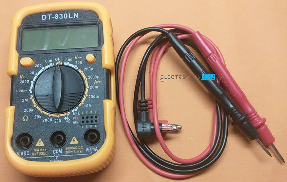
A Multimeter, also known as Multi tester, is an electronic measuring instrument which can measure Voltage, Current and Resistance. Hence, the name “Multi” meter, as it combines the functionalities of Voltmeter, Ammeter and Ohmmeter into a single device. It is a very essential tool for electrical and electronics engineers and is usually the first thing to use when troubleshooting a circuit. Multimeters come in different shapes, sizes and price points. There are bench Multimeters, handheld Multimeters and “clamp meters” in terms of different shapes and sizes. Coming to the price, basic Multimeters are available from as little as $5 while certified and calibrated Multimeters cost about $5,000. Irrespective of the size or price, every Multimeter can measure the most basic parameters like Voltage and Current. In addition to this, “modern Digital Multimeters (DMM)” allow you to measure resistance and also test for continuity. Using a Multimeter, you can
Check if the switch (or push button) is properly working or not. Measure the amount of current flowing through a device, like an LED. Measure the voltage of a battery. Check if the wire is conducting electricity or not.
Parts of a Multimeter
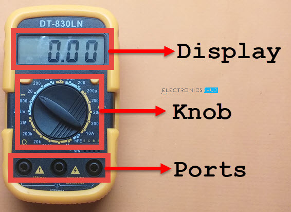
A basic Multimeter consists of four parts. They are:
Display Selection Knob Ports Probes
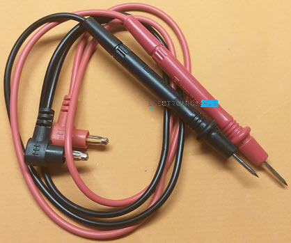
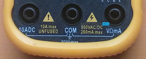
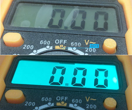
The measured value, whether it is voltage, or current or resistance, is displayed on the LCD Display of the Multimeter. You can set the parameter to measure using the selection knob at the center. Some advanced (and slightly costly) Multimeters can automatically adjust the range of the value being measured. These meters are known as Auto Ranging Multimeters. But in our basic meter, we have to manually set the range. Usually, every Multimeter comes with a pair of probes, one Red and one Black. Plug-in the probes in to ports of the Multimeter to make a measurement. Always connect the Black probe to the COM port. The Red probe is usually connected to the port with label VΩmA. In this configuration, you can measure AC and DC voltage, DC current in mA and Resistance, which is what most of us will use a Multimeter for. Use the other port with label 10ADC to measure DC Current up to 10A. WARNING: The 10A port will usually be marked whether there is an internal fuse or not. Be very careful when using this port and do not use this port for long continuous durations (not more than 10s). Some Multimeters come with backlight for the LCD display. This is useful if you are using the Multimeter in field with poor lighting.
How to use a Multimeter?
Now that we have seen a little bit about Multimeter and its parts, let us proceed with main topic i.e., how to use a Multimeter to troubleshoot our circuits. First, I will show you how to measure Voltage using a Multimeter. We will see the procedure for measuring both DC Voltage and AC Voltage. Then we will proceed to measure DC Current by building a small LED circuit. Finally, I will how you how to test for continuity. As a bonus, I will also show you how to test a Diode using DMM. So, let’s get started. Click Here To Know OHM Meter vs Multimeter
Measuring Voltage
Using a Digital Multimeter, you can measure both the DC and AC Voltage. The Voltmeter section of the Multimeter is usually marked as “V” and depending on AC or DC measurement, there will be additional indications.
DC Voltage
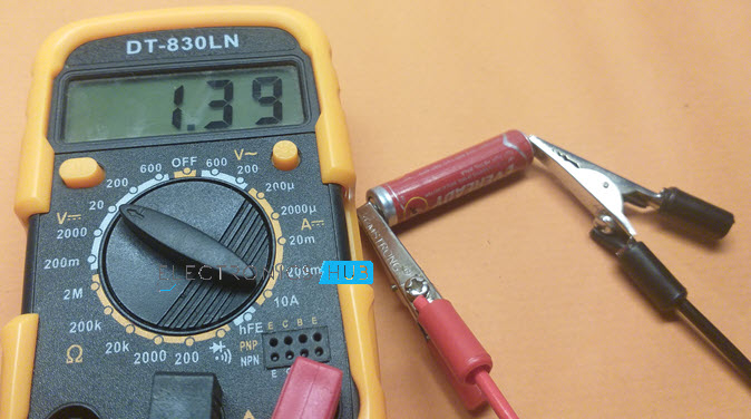
If there is a straight line adjacent to the “V”, then it is used to measure DC Voltage. Plug-in the correct probes into the Multimeter (if they are not already plugged in) and set the knob to measure DC Voltage. But there are a bunch of positions in DC Voltage measurement. Which one do you select? The number to which knob points to is the maximum value that we can measure of that particular parameter, DC Voltage in this case. So, if you set the knob to 20, then you can measure DC Voltages up to 20V. As you can see from the image, there are 5 positions associated with DC Voltage measurement (200m, 2000m, 2, 20, 200, 600). This particular Multimeter can measure a maximum DC Voltage of 600V. In case you want to measure the voltage of a 9V battery, then set the knob to 20. What happens if you set the range lower than the measuring value? In this case, the LCD will display 1, indicating that the result has exceeded the range. Now, connect the Red probe to the positive terminal of the battery and Black probe to the negative terminal. I took an old AAA battery for testing and connected the probes as mentioned above. The reading was 1.39V, which means the battery still has some charge (but not much).
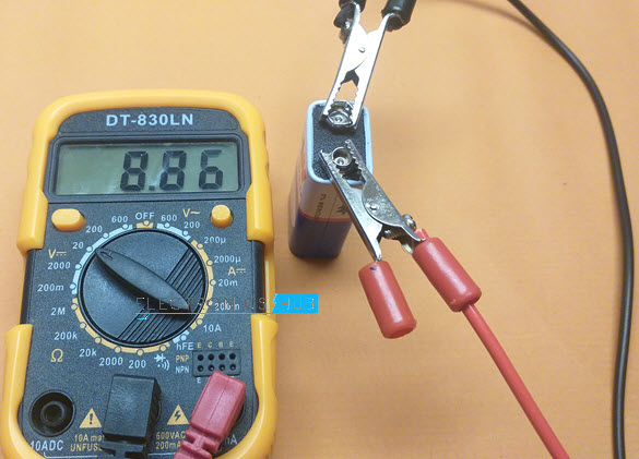
Now, what happens if you connect the probes in the other way? That is Red probe to negative terminal and Black probe to positive terminal. In this case, the Multimeter displays a negative value with same magnitude.
In a similar way, you can measure the voltage drop across components, voltage at a pin of a Microcontroller etc.
AC Voltage
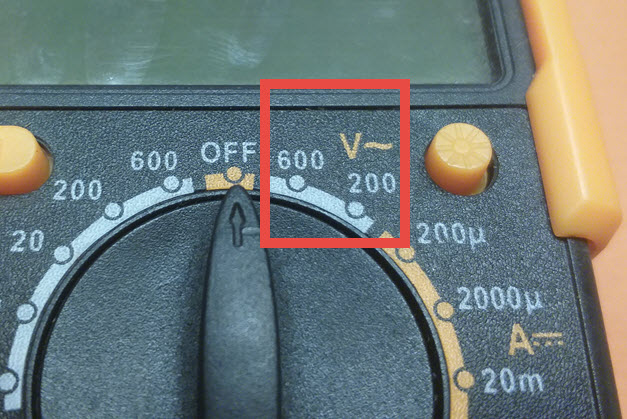
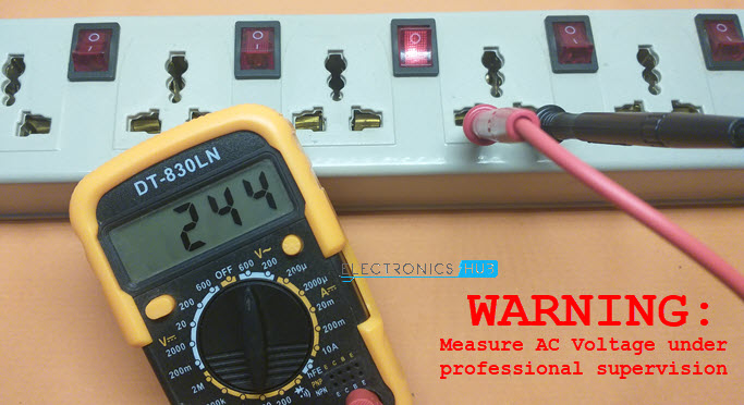
WARNING: Measure AC Voltage with extreme caution and preferably under a professional supervision. Make sure that the probes are properly inserted in to the Multimeter ports without any exposed metal. Do not touch the probes by the tips. AC Mains can be very dangerous. If in doubt, better not to use Multimeter for AC Mains Voltage measurement. A sine wave symbol adjacent to the “V” indicates AC Voltage measurement. As you can see from the image, this particular Multimeter can measure AC Voltage up to 600V and has only two range selection positions (200 and 600).
Let us measure the Mains AC voltage for the purpose of demonstration. Personally, I do not recommend beginners to go anywhere near Main AC. To measure AC mains Voltage, set the knob to 600 in AC Voltage Measurement (V with a Sine Wave). I chose 600 because my mains supply is 240V. Always set the knob for AC Voltage measurement before inserting the probes. Now, Insert the probes into the socket and you can see the measured AC Voltage displayed on the LCD.
Measuring Current
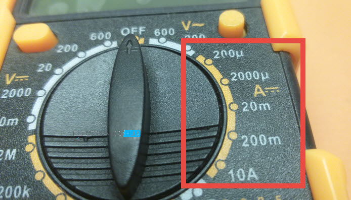
While measuring voltage is just placing probes at two different points of the circuit, measuring current is quite different. If you remember basic Circuit Theory, then you might remember that current in components connected in series is same. Using this basic principle, we have to make the Multimeter a part of the circuit so that same current passes through the Multimeter as in the component. The Ammeter section of the Multimeter is indicated by the symbol A. Another important point to note is that most Digital Multimeters can only measure DC Current. So, there will be a straight line adjacent to the A to indicate DC Current measurement.
DC Current
To measure DC Current, set knob of the Multimeter to DC Current measurement. This particular Multimeter can measure DC Current from few µA to 200mA. This range is sufficient for measuring current in LEDs.
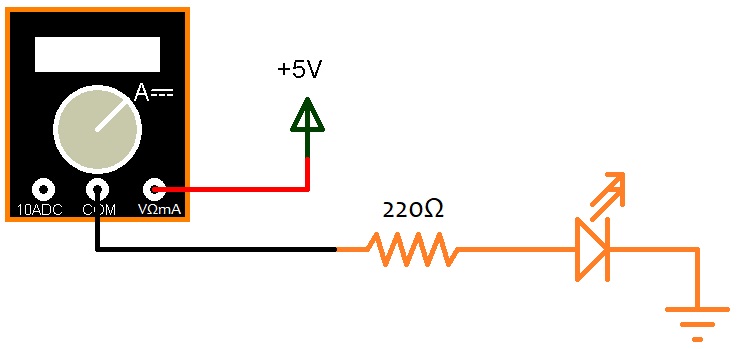
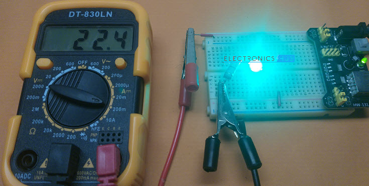
I set the range to 200mA and connected the Multimeter as per the following circuit. Consider the Multimeter in Ammeter mode as essentially a wire through which the current flows to the main circuit. In this configuration, Multimeter becomes a part of the circuit and if you disconnect any probe, then the circuit will not work. The measured current is displayed on the LCD.
Measuring Resistance
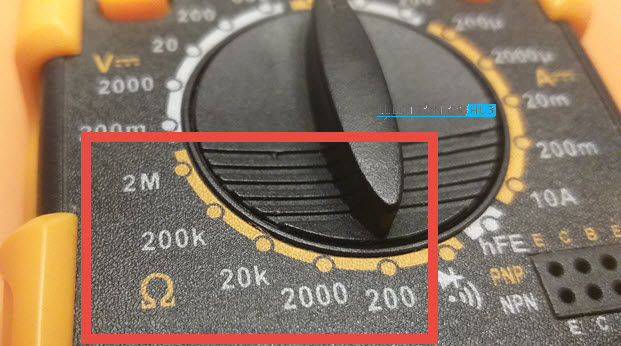
One of the easiest measurements you can perform using a Multimeter is that of a resistance. The Ohmmeter section of the Multimeter is represented by Ω symbol. This meter can measure resistance up to 2MΩ.
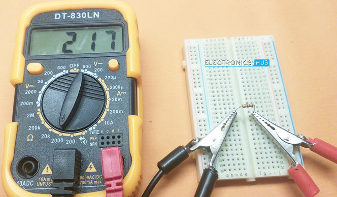
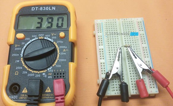
Set the knob to the desired range in the resistance measurement and connect the probes to the leads of the resistor. The measured resistance will be displayed on the LCD. You can connect the probes in any way as the result will not be affected by the orientation of the probes in case of resistance measurement.
Testing Continuity
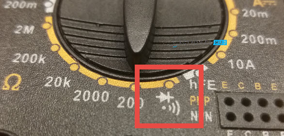
Perhaps the most frequently used and one of the easiest functions of a Multimeter is the continuity test. It is used to test continuity from point A to B in a circuit, whether a wire is conducting or not, whether a switch is properly functioning or not. The continuity test function is usually represented by a “speaker” symbol.
Set the knob to test for continuity and connect the probes across a wire. If the wire is in good condition without any breakage, then you will hear a continuous buzzer. If there is a problem in the wire, you won’t hear any sound.
How Continuity Test Works?
The continuity test is essentially a low resistance measurement. If the resistance between two points is very less (usually few Ohms), then those two points are considered as electrically connected and the buzzer starts the sound.
Diode Test
As a bonus, let us see the Diode Test feature of the Multimeter. Some Multimeters have dedicated diode testing functionality, which can be useful for checking diodes and some special types of transistors (as a transistor is essentially two diodes connected back-to-back). The diode test feature is usually combined with continuity test and is represented by a Diode Symbol.
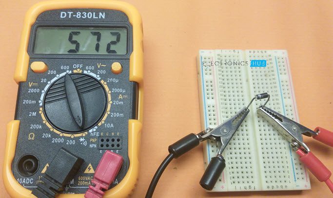
To test a diode, set the knob to Diode Test mode and connect the Red probe to Anode of the diode and Black probe to Cathode of the diode. If the diode is working properly, the Multimeter will display the forward voltage drop across the diode.
Conclusion
This article describes a complete beginner’s guide to using a Digital Multimeter for circuit troubleshooting. You learned how to use a Multimeter to measure voltage, current, resistance, continuity test as well as diode test. Regards Murray Thanks Noah Comment * Name * Email * Website
Δ
![]()
![]()
![]()

![]()
![]()

