One Transistor Electronic Code Lock System Circuit Principle:
The main principle of this circuit is that the door lock opens only when the buttons in series are pressed at a time. If any button which is in parallel is pressed door is locked. When all these buttons are pressed transistor switches the relay and the door is opened. In real time these buttons can be arranged in an order to open the door.
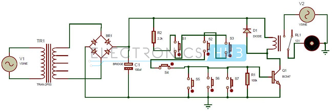
One Transistor Electronic Code Lock System Circuit Diagram:
Circuit Components:
Transformer. Bridge rectifier. Resistor. Capacitor. Buttons. Diode. Transistor. Relay. Motor Ac source.
Simple Transistor Code Lock Circuit Simulation Video:
One Transistor Electronic Code Lock System Circuit Design:
The circuit consists of a stepdown transformer whose input is AC supply of 230V and 50HZ. In the stepdown transformer, number of windings in the primary coil is less than the number of windings in the secondary coil. It is connected to the bridge rectifier. The bridge rectifier rectifies the full wave coming from the transformer .It has 4 pins in which two pins are connected to the transformer. In the other two pins, one is connected to ground and the other pin is connected to the resistor and capacitor. Capacitor other end is grounded. From the resistor, four buttons S1, S2, S3 and S4 are connected in series. Now from the next button S5, they are connected in parallel. Thus S5, S6, S7 are connected in parallel. A resistor of 100k is connected in parallel to the buttons. Base of the transistor is connected to the buttons in parallel. Emitter pin of the transistor is connected to the ground. Collector pin is connected to the 1N4007 diode, relay. Other end of the diode is connected to the one end of the relay. Here diode is used for protecting transistor, as relay produces back emf. Relay has five pins. One pin is connected to the positive terminal of the diode. Other pin is connected to the ground. Thus relay output is connected to the motor through its AC source. The relay used here is a magnetic relay. It has five pins i.e. NC, NO, COM, A, B. A, B are the inputs of the coil .When no voltage is applied to these pins, COM pin is connected to the normally closed pin i.e. NC pin. When a DC voltage is applied to A, B pins of the relay, the COM pin is connected to the normally open pin i.e. NO pin of the relay.
Simple Transistor Electronic Code Lock System Project Output Video:
How One Transistor Electronic Code Lock System Circuit Works?
Electronic Code Lock System Circuit Advantages and Applications:
This circuit is very simple, reliable and low cost. We can use it in security applications. We can also use it in door lock systems to open the door.
If the user forgets the password i.e. the order of the buttons to be pressed it is difficult to open the lock.
if u don’t know, don’t explain wrong concept.. Diode is used parallel with relay in reverse polarity in order to avoid high reverse flow of voltage when diode switched off.. relays having a bad property of generating high voltage of 4 times the voltage we applied. when they turned off, that voltage will defiantly damage the remaining components .. that is the actual reason we use a diode. Comment * Name * Email * Website
Δ
![]()
![]()
![]()
![]()
![]()

