Introduction
There can be any sudden situation of panic. It could be because of an intruder entering our house or bad health status. Situations can be many for panicking and may vary from person to person. During such emergencies, we might be unable to intimate to the people around us. In this article we shall see how to make a simple panic alarm, which can help us to intimate others regarding our bad situation without any delay.
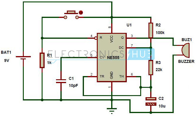
Panic Alarm Circuit Diagram
Components Required
555 IC Resistor – 1KΩ Resistor – 22KΩ Resistor – 100KΩ Capacitor – 10µF 9V Battery Push Button Mini Buzzer Breadboard Connecting Wires
Design
This circuit is made with a low cost hardware using IC 555 timer, buzzer, a few resistors and capacitors. It is made to be working reliably as it has simple to use and not so sensitive hardware like 555 timer, ceramic buzzer, capacitors, etc. Although no exclusive arrangement is used to make any compensation for the variable parameters, the circuit by default is made to be robust and easy to use. It is very user friendly with a single button to be pressed to handle the panicking situation without any trouble.
Working
The IC 555 is used in the Astable mode with the frequency depending on the values of resistors R2, R3 and C2. The values of R2 = 100KΩ, R3 = 22KΩ and C2 = 10µF. By substituting the given parameters in the respective formulas for IC 555 in astable mode, we get the following values. The frequency of operation of the circuit is calculated to be 1 Hz. By finding the time period of the circuit by using the frequency information, we get the time period of the circuit as 1 second. This means the circuit has a on -off repeating time period of about 1 second.
After analyzing the ON and OFF time period of the panic alarm circuit given above, we find that the circuit will remain on for about 0.845 seconds and off for about 0.152 seconds. The circuit is in the disabled mode when the button is not pressed and hence the alarm will not function when the button is not pressed. Although the power supply will be supplied to the IC 555 all the time, the circuit will operate in the astable mode only when the IC is enabled. The IC is in the enable mode only when pin 4 of the 555 IC is given a high voltage. This happens only when the button is pressed. The button can be made to have a plastic enclosure to have a better visibility and ease of access to it. For the purpose of demonstration, I have connected a simple Buzzer to the output of the 555 IC. Comment * Name * Email * Website
Δ
![]()
![]()
![]()

![]()
![]()

