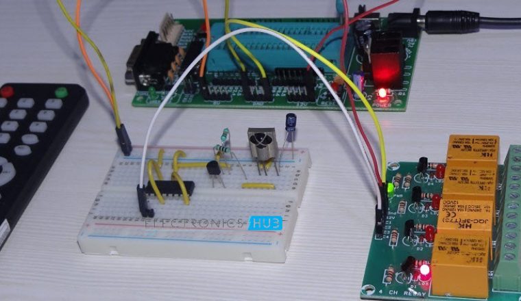
Normally, we use remote controls to turn ON or OFF appliances like TV, DVD Player, Music System, etc. But in this project, we have designed the circuit such that whenever a button on the remote is pressed, the AC Light will turn ON or OFF. Caution: Be careful while connecting AC lines to Relay and Light. Take necessary precaution when connecting AC Mains to relay. It is a small circuit with simple hardware and minimal construction. The main components of the remote controlled light switch circuit are IC CD 4017 Decade Counter, TSOP 1738 Infrared receiver, Relay Modules, mini remote and few other minor components. Remote Controlled Light Switch 1Remote Controlled Light Switch 2Remote Controlled Light Switch 3Remote Controlled Light Switch 4Remote Controlled Light Switch 5Remote Controlled Light Switch 6
Circuit Diagram
The circuit diagram of the remote controlled light switch is shown in the following image. It consists of the receiver part of the circuit and load control part.
Components Required
IC CD 4017 Decade Counter TSOP 1738 Infrared Receiver Mini Remote Control 2N2222 NPN Transistor BC558 PNP Transistor 1 KΩ Resistor (1/4 Watt) x 2 10 KΩ Resistor (1/4 Watt) 1N4007 PN Junction Diode 12V Relay AC Light Bulb Bulb Holder
Component Description
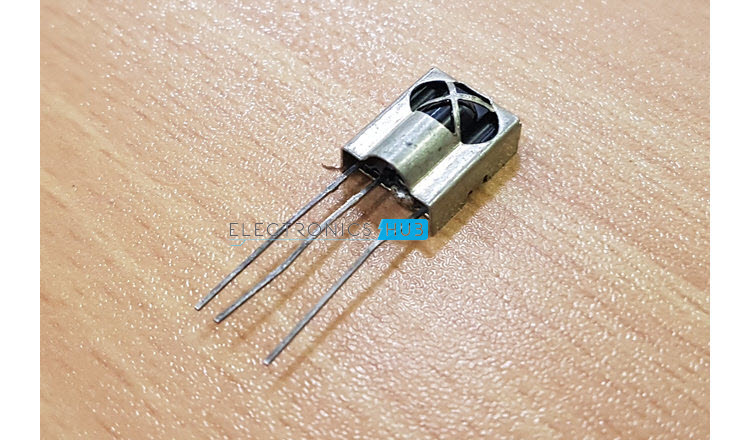
IC CD4017: IC 4017 is a high voltage decade counter IC which produces 10 decoded outputs for a positive transition on the clock. It is a 16 pin IC available in dual – in – line (DIP) package. More information about IC 4017 can be found here. TSOP 1738: TSOP 1738 is a 38KHz Carrier Frequency Infrared Receiver, often used in Infrared communication. They are often used in TVs, Hi-Fi systems, DVD/CD Players and other remote control applications. More information about IR Transmitter and receiver can be found here.
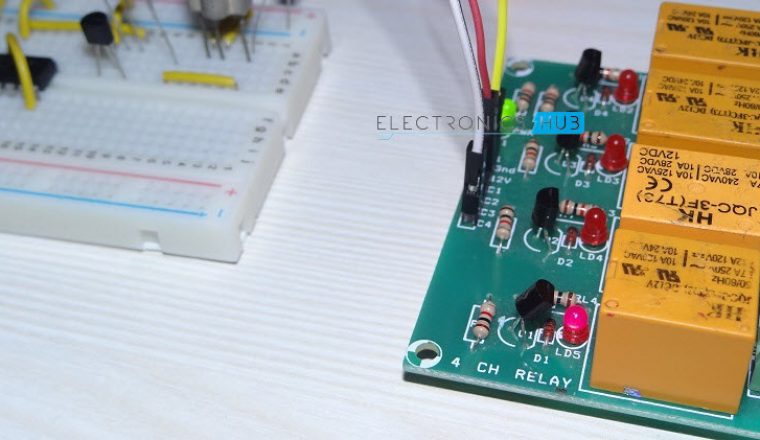
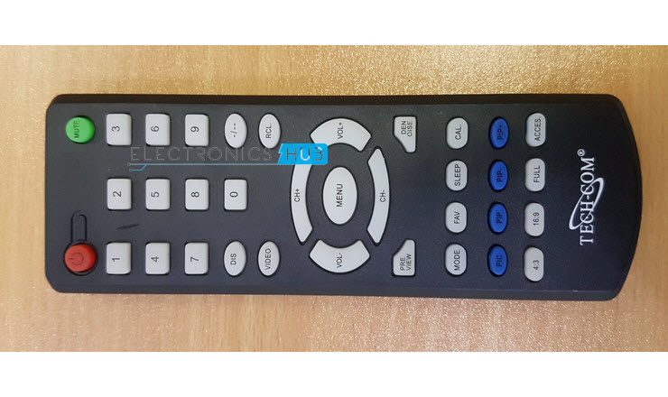
Mini Remote Control: A small remote control is used to transmit Infrared signals. Any remote can be used for this purpose as TSOP 1738 supports a wide range of modulating techniques. NOTE: There is no need for the remote and it is just a convenience. A simple IR LED with 38 KHz pulse can be used as a remote control. Relay Module: A 4 channel Relay Module is used in this project in order to control the Light. A single channel relay board is sufficient. Alternatively, the relay circuit can be built as per the circuit diagram.
Circuit Design of Remote Controlled Light Switch
The main components of the project are IC CD4017 and TSOP 1738 IR Receiver. The output of the IR Receiver is a decoded output of the signal from Remote control. This decoded output is given to a PNP transistor at its base through a 1 KΩ resistor. Also, a capacitor is connected between the output of TSOP 1738 IR Receiver and ground in order to smooth the output signal. The output of the transistor i.e. the Emitter is connected to the Clock input of the Decade Counter IC 4017. The Clock Inhibit or Enable Pin is connected to ground. The output 2 of IC 4017 i.e. Q2 (Pin 4) is connected to Reset pin (Pin 15). Finally, the output 1 i.e. Q1 (Pin 3) is connected to the input of the relay module. NOTE: We have used a pre – constructed Relay Board with all the components like Transistor, Diode, resistor, etc. are already embedded on it. Caution: Be careful when connecting AC Mains to the Relay Board.
Working of the Project
A simple application where a remote control is used to turn ON or OFF an AC Light is designed in this project. The working of the project is pretty straight forward and is explained here. Whenever a button is pressed on the remote control, it transmits modulated Infrared Signals. When this modulated signal is detected by the IR Receiver TSOP 1738, it demodulates the signal and produces an appropriate output. The output of the TSOP 1738 is LOW whenever it detects and demodulates the Infrared signal. Since this output is connected to the input of the PNP transistor (BC558), it is tuned ON whenever any button is pressed on the remote control. As a result, the clock pin of the IC 4017 Decade Counter receives a positive transition. This makes the output Q1 to go HIGH. Since Q1 of IC 4017 is connected to input of the relay board, the relay is activated and turns ON the light (or any other load connected to it). Now, when a button is pressed on the remote control, the output of the TSOP goes LOW once again the PNP transistor is once again turned ON. The Clock of the IC 4017 once again receives a low to high transition. Now, the output Q2 will become HIGH. Since, the output Q2 is connected to the RESET pin of the IC 4017, the Decade Counter IC will be reset and the Output Q1 becomes LOW. As a result, the Light is turned OFF. If any button is pressed once again, this time, since the IC is reset in the previous stage, the Output Q1 will go HIGH, turning ON the Light. The cycle continues and push to ON and push to OFF is achieved.
Advantages
Remote Control of Light (or any load) is possible with this circuit. By implementing a similar circuit with the help of a Microcontroller, multiple loads can be controlled i.e. each button can be assigned to turn ON or OFF a different load. For Arduino based implementation of the same application visit:Arduino based home automation https://www.electronicshub.org/arduino-based-home-automation-using-tv-remote/
Disadvantages
Since there is no Microcontroller, the data from the decoded signals can’t be determined. And hence, there is now way to differentiate which button is pressed. As a result, the Light will be turned ON or OFF when any button is pressed. For the same reason, only a single load can be controlled. Since the communication is Infrared, it required line – of – sight communication and also the range is limited (very small).
Comment * Name * Email * Website
Δ
![]()
![]()
![]()


![]()
![]()

