The need for speed control of DC motors has to do with the application in which the DC motor is used. For example, consider a simple DC Motor is used as a cooling fan in hardware like computers, laptops, etc. In this case, if there is no concept of speed control, the motor (or fan, in this case) runs either at full speed or stops rotating. But if we introduce the speed control of the motor, we can run the motor or fan at slower speeds under normal conditions and at higher speeds when required. There are many other applications of speed control of DC Motor. The aim of this project is to control the speed of a DC Motor using the LPC2148 MCU with the help of a potentiometer.
Circuit Diagram
Components Required
Depending on the type of MCU board you are using, you might need some or all the components mentioned below.
Lpc2148 MCU based Development board or stand – alone board 12 V DC Motor 2N2222 NPN Transistor 1 KΩ Resistor 10 KΩ Potentiometer Power supply (Separate for MCU and Motor) Connecting wires USB Type A – to – mini USB Cable
Circuit Design
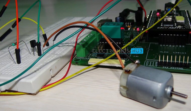
We are using an LPC2148 development board in this project. The design of the circuit involves connecting the potentiometer and the motor to the MCU. Since the input from the potentiometer is an analog signal, we need to connect the output of the potentiometer to one of the analog input pins i.e. one of the ADC pins of the LPC2148 MCU. On the development board we are using, a Potentiometer is already present and the output of the potentiometer is connected to pin P0.28 i.e. AD0.1 channel. After connecting potentiometer, we need to connect the motor to the MCU. Since we cannot connect the motor directly to the LPC2148 (as a matter of fact to any microcontroller), we need to use a driver circuit. As this is a simple speed control of the DC motor, we can connect the motor with a transistor provided the transistor can handle current requirements of the motor. Hence, we chose 2N2222 transistor. It is an NPN transistor with a maximum collector – to – emitter voltage of 30V and a maximum collector current of 800mA. Note: The current required for a simple 12V DC Motor will be in the range of 400mA to 600mA (this is a typical range and the actual requirements may vary with the type of motor). Hence, 2N2222 Transistor can handle the requirements of the motor.
Working of the Project
Speed control of a simple DC motor is demonstrated in this project. The project involves ADC and PWM modules of the LPC2148 MCU. The working of the project is explained here. As mentioned earlier, the output of the potentiometer is an analog signal. This must be converted to a digital signal using the on – chip ADC module of the ARM7 MCU LPC2147. Using the registers corresponding to ADC module, the ADC is setup, values are converted and the result is obtained. More information about ADC in LPC2148 can be found here. The next important module is the PWM generator. PWM signal can determine the amount of power that gets delivered to a device. In this project, the PWM signal will control the speed of rotation of the DC motor. This is done by setting the duty cycle of the PWM output signal. The output of the ADC will determine the duty cycle of the PWM signal. More information about PWM in LPC2148 can be found here. The working of the project can be understood better if we analyze the programming part of it.
Code
Understanding the Program
As mentioned earlier, we need to use ADC and PWM modules of the LPC2148 MCU. Apart from these, we also need to use the PLL for clock generation. As explained in our PLL Tutorial, setting up PLL module for generating system clock is a very simple task. All we need to do is set the following registers with the specified values. Each instruction is explained briefly with an adjacent comment. For more information, you can visit our LPC2148 PLL tutorial. PLL0CON = 0x01; // Enabling PLL0 Module PLL0CFG = 0x24; // MUL and DIVVAL values are set for clock generation PLL0FEED = 0xAA; // Feed sequence for locking the MUL and DIVVAL PLL0FEED = 0x55; while (!(PLL0STAT & 0x00000400)); // Waiting for the PLL0 module to get locked to the values PLL0CON = 0x03; // Enabling the PLL0 module again and Connecting it for clock generation PLL0FEED = 0xAA; // Feed sequence for locking the status of the PLL0 module PLL0FEED = 0x55; VPBDIV = 0x01; // Finally, making the Peripheral clock same as system clock With the above set of instructions, we will have successfully setup the system clock and the peripheral clock to run at 60 MHz. The next module is the ADC module. The steps for initializing the ADC module and getting the converted output value are clearly explained in our LPC2148 ADC tutorial. By following those steps and referring the instructions in this program, you can easily understand how ADC module is used in this project. Finally, the last module we used in this project is the PWM. First, the appropriate PWM channel is selected using the PINSEL register. Next, the default Period of the PWM is set as 255. After that, the result from the ADC is given as the duty cycle input to the selected PWM channel after dividing it by 4 (since the output of ADC is 10 – bit value (1024 values) and PWM is only 8 – bit (255 is maximum)). In the code (program), each instruction is briefly commented for better understanding. Comment * Name * Email * Website
Δ
![]()
![]()
![]()


![]()
![]()

