To control and maintain such complex street lighting systems, various street light control systems are developed. In this project, we are going to develop a project called Street Light Control using 8051 Microcontroller, in which the street lights are automatically turned ON or OFF based on the movement of the vehicles. The important considerations in the development of street light control systems are Automation, Power consumption and Cost Effectiveness.
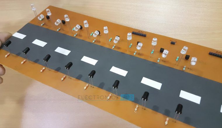
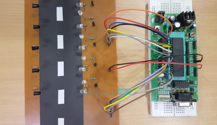
Construction and Output Video
Principle of Operation
The principle behind the working of the project lies in the functioning of IR Sensor. We are going to use a Transmissive type IR Sensor in this project. In Transmissive IR Sensor, the IR transmitter and receiver are placed facing each other so that IR receiver always detects IR Rays emitted by the IR Transmitter. If there is an obstacle between the IR Transmitter and Receiver, the IR Rays are blocked by the obstacle and the IR Receiver stops detecting the IR Rays. This can be configured to turn ON or OFF the LEDs (or street lights) with the help of microcontroller.
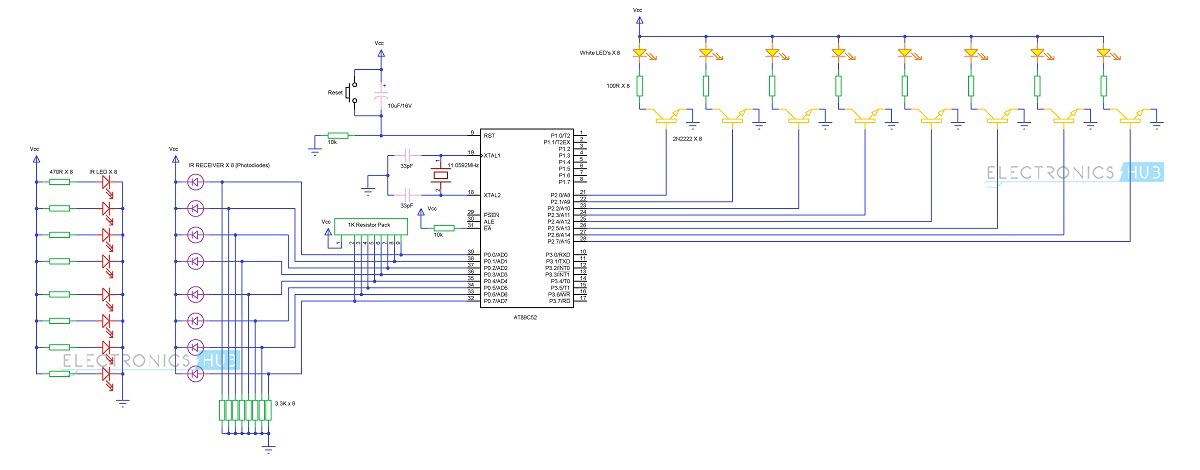
Circuit Diagram
Components
Circuit Design
The main components of the project are AT89C52 Microcontroller, IR Sensor (IR Transmitter and IR Receiver) and LEDs. The basic connections required for 8051 Microcontroller involve crystal, reset and External Access. In order to use the on-chip oscillator, the 8051 microcontroller requires an external clock. This is provided by a crystal oscillator. An 11.0592MHz quartz crystal is connected to XTAL1 and XTAL2 pins with two 22pF ceramic capacitors connected to it. The reset circuit of the microcontroller consists of a 10K resistor, 10uF capacitor and a push button. All the connections of the reset circuit are shown in the circuit diagram. External access Pin is used to access external memory when it is connected to ground. Anyway, we are not going to use any external memory here. So, connect this pin to Vcc via a 10K resistor. The next hard ware we are going to connect is the IR Receiver. We are going to connect the 8 IR receivers to port 0 pins of the microcontroller. In order to use the PORT0 as I/O port, we need to connect external pullup resistors to the port 0 pins. s After that, connect the output of the IR receiver i.e. anode terminal of the photo diode to port 0 pins. Cathode terminals of the photo diodes are connected to supply. Also, a 3.3k Resistor is connected between the anode terminal and ground. The next part of the circuit is IR transmitter. IR transmitter is not a part of the microcontroller connections as the only job of the IR transmitter is to continuously emit infrared rays. Hence, connect the 8 IR transmitters with corresponding 8 current limiting resistors of 470 ohms with a power supply. Finally, we need to connect the LEDs. We need to connect the LED’s with the help of transistors to the PORT2 of the microcontroller. The base of the 8 2N2222 transistors is connected to the PORT 2 of the microcontroller while the emitters of the transistors are connected to ground. An LED along with a series current limiting resistor of 100 ohms is connected to the each of the collector terminal of the transistor.
Working
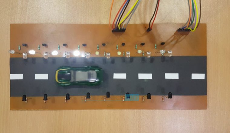
The aim of this project is to design a street light control system using 8051 microcontroller, which automatically turns on or off the street lights by detecting the movement of vehicles. The working of the project is explained here. Below GIF demonstrates the working of the project.
The IR transmitter is placed directly in line of sight with IR receiver, so that the IR receiver continuously receives infrared rays. Once the IR receiver receives infrared rays, the microcontroller will detect Logic 1. If the infrared rays are blocked by some means, the microcontroller will detect logic 0. So, the program for the microcontroller must be written in such a way that it will turn ON the LEDs, which means here the street lamp, when it detects Logic 0 and it will turn OFF the LEDs, when it detects Logic 1. Consider the two IR sensors i.e. IR Transmitter and IR Receiver are placed on the either side of the road. As per the circuit diagram, the IR receivers are connected to the PORT0 and the LEDs are connected to the PORT2 of the microcontroller. At the beginning, when there is no obstacle, the IR receiver continuously detects IR light transmitted by the IR Transmitter. When a car or any other vehicle blocks any of the IR sensor, the microcontroller will turn ON the immediate three LEDs. If the car blocks the first IR sensor, the first three LEDs are turned ON by the microcontroller. As the car moves forward and blocks the second IR sensor, the corresponding next three LEDs will be turned ON and the first LED of the previous set is turned OFF. The process continues this way for all the IR Sensors and LEDs.
Applications
Main Advantages of this Circuit
If the lighting system implements all LED lights, the cost of the maintenance can be reduced as the life span and durability of LEDs is higher than Neon based lights which are normally used as street lights. As the lights are automatically turned ON or OFF, huge amount of energy can be saved.
Comment * Name * Email * Website
Δ
![]()
![]()
![]()

![]()
![]()

