Additionally, I will show you how to adjust the contrast of Nokia 5110 LCD Display using a potentiometer.
If you want to learn how to interface Nokia 5110 LCD Display with ESP32 DevKit Development Board, then I made a separate tutorial for that. Check it out.
A Brief Note on Nokia 5110 LCD
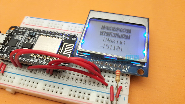
The PCD8544 LCD Controller based Nokia 5110 LCD Display is a very useful graphical display with a resolution of 84 x 48 pixels. It runs on 3.3V, so, connecting it with ESP8266 won’t be a problem. It is one of the simplest display devices you can interface with ESP8266 and requires a very minimal setup.
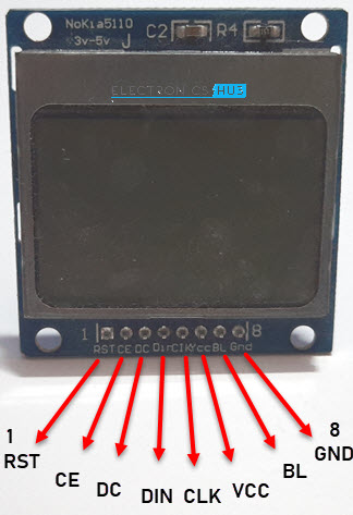
To communicate with a microcontroller, the PCD8544 Controller uses SPI like serial interface. The following image shows the pinout of Nokia 5110 LCD Display. Table below contains the Pin description of all the pins of Nokia 5110 LCD. The naming may be different but the interface is very similar to SPI. In fact, we will be using SPI peripheral of ESP8266 to connect with Nokia 5110.
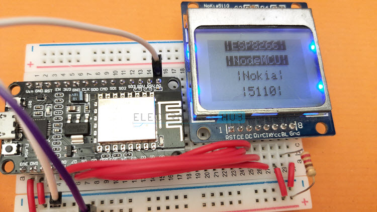
NodeMCU ESP8266 Nokia 5110 LCD Interface
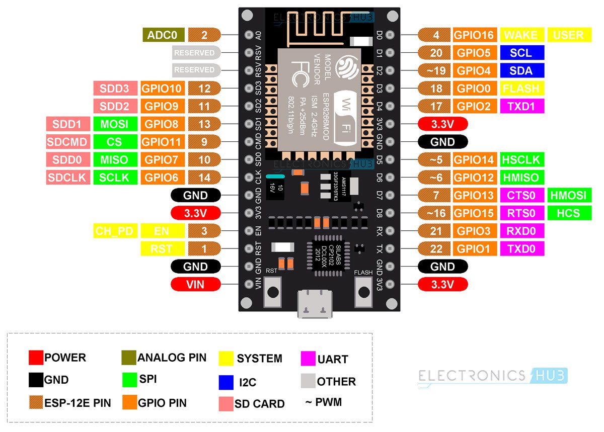
As mentioned before, the Nokia 5110 LCD has a serial communication interface which is similar to SPI. Hence, we have to identify the SPI Pins of ESP8266 NodeMCU Board. ESP8266 SoC has two SPI Interfaces:
SPI HSPI
SPI is already used for interfacing SPI Flash on ESP-12E Module. So, we are left with HSPI. If you take a look at the pinout of NodeMCU ESP8266, then GPIO Pins 12 to 15 are associated with HSPI.
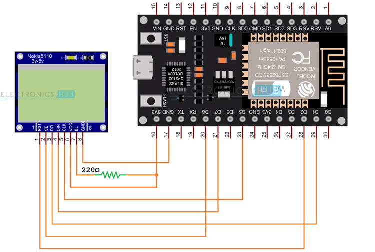
In this, we will be using the MOSI, SCK and CS pins. Additionally, there are two pins on Nokia 5110 LCD known as RST and D/C. These pins are not associated to SPI hardware and hence we can use any GPIO pins which are free. So, the final connections between NodeMCU ESP8266 and Nokia 5110 LCD look something like this: If you notice the table, I also mentioned that the ‘BL’ Pin of Nokia 5110 LCD, which enables the backlight, is connected to 3.3V through a 220Ω current limiting resistor (just to be on the safe side).
Components Required
NodeMCU ESP8266 Development Board Nokia 5110 LCD Display 220Ω Resistor Breadboard Connecting Wires 10 KΩ Potentiometer (for setting contrast)
Circuit Diagram
The following image shows all the necessary connections for ESP8266 Nokia 5110 LCD interface.
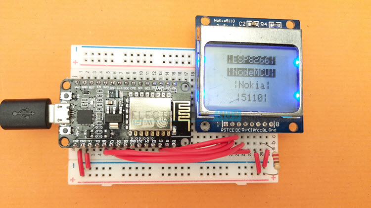
Displaying Text on Nokia 5110
Let us now see how easy it is to display text on the Nokia 5110 LCD. The ‘Adafruit_PCD8544’ library significantly reduces the complexity of the PCD8544 LCD Controller IC and exposes simple functions to the user. Some of the important functions are:
begin: To setup SPI interface and initialize the display. display: Update the display. print: Print / Display text on screen. clearDisplay: Clears entire display. setContrast: Set the Contrast level of the display. setCursor: Set the text cursor location
NOTE: Visit github page of ‘Adafruit_PCD8544’ library for more information. Using these and many other functions, we can display text, ASCII Characters, Custom Characters, Set the size of Font, Change the Font etc. Additionally, the ‘Adafruit_GFX’ library allows you to display basic graphics like individual pixels, line, circle, rectangle, tringle etc.
Code
The following is a simple code to display text on Nokia 5110 LCD using ESP8266 NodeMCU Board.
Adjust Contrast of Nokia 5110
Next, we will see how to adjust the contrast of Nokia 5110 LCD. We will use a 10 KΩ potentiometer to set the contrast. First, we will display some text on the LCD, then we will connect the POT to ADC Pin of ESP8266. In the program, we will read the Analog Input from the potentiometer, convert it to digital value (using ADC) and map the result of ADC to appropriate contrast value. It is very simple. It is one way to adjust the contrast of the display. You can also use other methods like push buttons, serial communication etc. NOTE: ESP8266 has only ADC Channel and its resolution is 10 bits i.e., the output of ADC of ESP8266 will be in the range of 0 to 1023. So, using the Arduino’s ‘map’ function, we can convert this range to a more suitable range for contrast (which is 0 to 100).
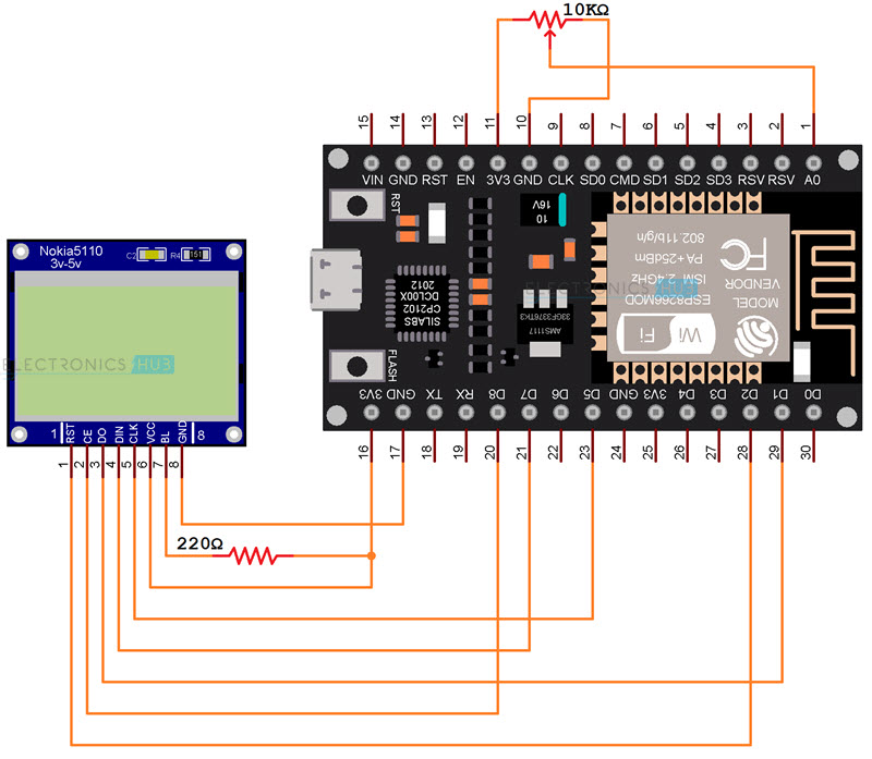
Circuit Diagram
Connections for adjusting contrast of Nokia 5110 LCD Display using ESP8266 and potentiometer are shown in the following circuit diagram.
Code
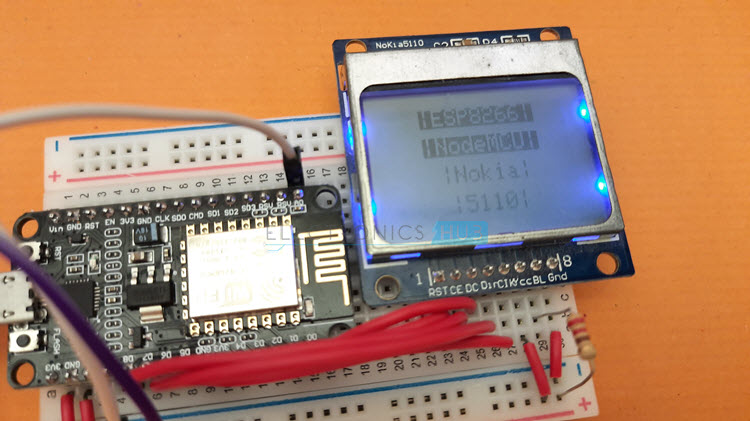
The following image show a lower contrast setting on Nokia 5110 LCD.
Similarly, we can even increase the contrast just by turning the potentiometer. The following image shows a higher contrast setting.
Conclusion
A simple project to understand how to interface Nokia 5110 LCD with ESP8266 NodeMCU Board. You learned the pinout of Nokia 5110 LCD, the connections between ESP8266 NodeMCU and Nokia 5110, how NodeMCU ESP8266 Nokia 5110 LCD Display interface works, how to display some text on the LCD and also how to adjust the contrast of Nokia 5110 using a POT. Comment * Name * Email * Website
Δ
![]()
![]()
![]()
![]()
![]()

